


引言
对于年龄较大的儿童或青少年,Y型软骨闭合后,一般采用髋臼周围截骨术(periacetabular osteotomy,PAO)进行治疗.PAO即伯尔尼髋臼周围截骨术,又称为Ganz髋臼周围截骨术(Ganz PAO)[3],是瑞士医师 Reinhold Ganz和Jeffrey Mast在1988年提出的髋臼重建的主要手术方法之一.其主要是通过在髋臼周围做髂骨、耻骨和坐骨的截骨,将髋臼从周围的骨盆中分离出来,截取的髋臼可以大幅度旋转,即可有效改善髋臼对股骨头的覆盖,增加关节稳定性,减少单位面积负荷.由于截出的髋臼节段大,缺血性坏死发生的风险大大降低.PAO是以中心边缘(center edge,CE)角度来评估髋臼和股骨头的相对位置,同时反映髋臼对股骨头的覆盖情况.目前髋臼旋转时的方向和角度没有具体的量化标准,主要依靠外科医生的经验和感觉在非直视条件下通过定向骨折来完成截骨,难以使股骨头达到最理想的覆盖.对于旋转后的髋臼是否存在过度前倾、后倾,或者过度包容也只能通过透视观察包容情况和关节活动度来判断.若髋臼过度外移,可能会引起髋关节外展肌力减弱.因此,评估Ganz PAO手术过程中截取髋臼旋转时生物力学的变化对术前制定有效的手术方案具有重要意义.
由于该方法在分析不规则物体的力学特点方面具有优越性,已在骨骼尤其是在模拟和计划髋关节外科手术的生物力学研究中得到广泛应用.目前大多数研究是基于计算机断层扫描(computed tomography,CT)图像建立三维结构模型,然后进行生物力学分析.如Zhao等[8]基于CT图像对PAO前后皮质骨应力分布的变化进行生物力学评估,并利用三维有限元分析确定DDH严重程度对应力分布的影响.Lee等[9]基于患者的CT图像构建PAO前后髋关节有限元模型,以定量的方式获取了手术前后关节接触面积、CE角和耻骨联合与股骨头之间距离的几何变化,以评估疗效.Liu等[10]利用之前工作中开发的计算机辅助规划和导航系统,基于患侧髋CT图像构建三维有限元模型,用于模拟关节间的接触压力和接触面积,以确保PAO手术中髋臼的精准重新定位.Park等[11]基于CT图像构建手术前髋关节特定有限元模型,模拟PAO期间的髋臼旋转,生成12个术后虚拟有限元模型,以找到最佳手术位置.Kitamura等[12]在患者特定的三维髋关节模型上进行3种模式的虚拟PAO,利用有限元分析计算单腿站立时髋关节软骨间的接触压力,以确定冠状面髋臼矫正与关节接触压力之间的关系.国内也有部分学者对髋关节生物力学进行了一定的研究.Tian等[13]基于1位DDH患者CT图像,按照建模完整程度的不同,建立了2个三维模型,通过有限元法研究两个模型在单腿站立姿态下髋关节的生物力学特性,并模拟截骨,分析两种建模方式对术前规划结果的影响.Zhang等[14]基于CT图像建立了DDH患者的三维有限元模型,并通过旋转截骨块构建了不同PAO方案的术后模型.在单腿受力条件下分析了手术前后髋关节周围软骨的受力变化,并与正常髋关节模型进行比较.上述研究通过有限元方法在PAO的生物力学研究方面取得了重要进展,但存在一些需要克服的局限性.第一,以往研究主要关注点在寻找PAO术中髋臼最佳旋转位置,均未考虑PAO后髋关节的正常活动.第二,部分研究中DDH三维模型是基于正常髋关节CT图像通过计算创建的,这与真实患者患侧髋生理情况存在差异.第三,在基于CT图像建立患者髋关节三维模型时,为了区分皮质骨和松质骨,大多数研究直接利用逆向工程建模软件从模型外层向部件内部均匀缩小,与髋关节真实的解剖学三维结构不符.但通过磁共振成像(magnetic resonance imaging,MRI)数据,可分别建立骨皮质和骨松质的三维模型.MRI基本原理是利用氢质子成像,骨皮质含有大量的钙而其中水分含量极低,在T1加权图像上呈低信号;骨松质本身无氢质子成分,但骨髓内部含有大量脂肪和水,在T1加权图像上呈高信号,因此在MRI图像上骨皮质和骨松质之间有明显的界限.但因MRI图像建模难度较大,到目前为止使用MRI图像进行髋关节有限元分析的研究仍很少.
本文充分发挥MRI的优势,利用DDH患者的髋关节MRI图像获得病灶部位骨骼皮质、松质的结构信息,所构建的骨骼结构模型更符合患者的实际情况.通过有限元分析模拟PAO手术过程以确定髋臼重新定向的位置,并在以往研究的基础上,进一步研究了PAO术后髋关节的正常活动,对基于患侧髋MRI图像构建的术前模型和通过模拟获得最佳髋臼位置的计划模型在髋关节6个运动方向下的接触压力和接触面积进行了比较,以验证为DDH患者进行虚拟手术规划的有效性.
1 实验部分
1.1 建模材料
1.1.1 研究对象与数据采集
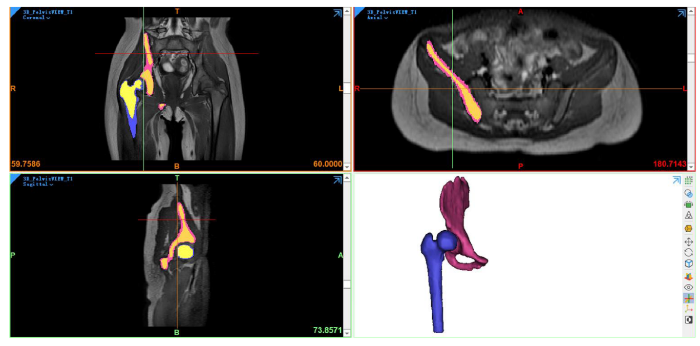
选择一名10岁髋关节右侧患有DDH的儿童,性别女,体重26 kg,患侧髋的CE角为5.5°.CE角即股骨头中心到髋臼外上缘连线与经股骨头中心的垂线所形成的夹角,是通过基于MRI图像构建的模型得到的,如图1所示.患者取仰卧位,采用Philips 3.0 T磁共振成像设备行骨盆MR扫描(包括双侧股骨上段),脉冲序列为3D_PelvisVIEW_T1,其基础序列为快速自旋回波,参数设置如下:层厚为1 mm,重复时间为400 ms,回波时间为19.967 ms,翻转角为90°,采集矩阵为251×251,回波链长度为30.本研究获得苏州大学附属儿童医院医学伦理委员会的批准(批准文号:2016KS014).
图1

1.1.2 软件
Mimics Medical 21.0(Materialise公司,比利时)用于医学图像的三维建模;3-matic Medical 13.0(Materialise公司,比利时)用于软骨重建;Geomagic Studio 2013(Geomagic公司,美国)用于模型优化,形成三维实体模型;ANSYS Workbench 19.2(ANSYS公司,美国)用于有限元模型前处理、计算和后处理.
1.2 实验方法
1.2.1 髋关节三维实体模型的构建
图2
如图3所示,髋部有两个关键的软骨区域,都在关节部位;第一个在股骨头上,第二个在骨盆髋臼.出现在关节(如髋关节)表面的软骨是透明的软骨,它为关节提供一个光滑的润滑面,便于关节运动.Liu等[10]发现恒定厚度软骨模型和患者特异性软骨模型之间的生物力学优化结果具有很强的相关性.为了模拟髋骨(蓝色)和股骨(绿色)两块骨骼之间的关节,在3-matic软件中通过髋臼和股骨头表面网格的偏移,创建了厚度为1.5 mm的髋臼软骨(灰色)层和股骨软骨(棕色)层.最后,将以上生成的部件以STL格式输出,导入Geomagic软件进行去噪、平滑等处理以优化模型几何结构,并将片体模型转换为三维实体模型.为减少计算量,裁剪了部分非重点研究部位.
图3

1.2.2 材料赋值
表1 人体髋关节有限元模型的材料属性和单元类型
Table 1
| 部件 | 单元类型 | 杨氏模量/MPa | 泊松比 |
|---|---|---|---|
| 皮质骨 | 四面体 | 17000 | 0.3 |
| 松质骨 | 四面体 | 70 | 0.2 |
| 软骨 | 四面体 | 15 | 0.45 |
表2 髋关节韧带的材料属性
Table 2
| 韧带 | 韧带刚度/(N/mm) | 数量 | 弹簧刚度/(N/mm) |
|---|---|---|---|
| 圆韧带 | 68 | 1 | 68 |
| 坐股韧带 | 39.6 | 10 | 3.96 |
| 耻股韧带 | 36.9 | 6 | 6.15 |
| 髂股下韧带 | 100.7 | 4 | 25.175 |
| 髂股上韧带 | 97.8 | 4 | 24.375 |
1.2.3 边界条件设置
Bergmann认为髋关节的关节反应力与体重直接相关,当人单腿站立时,髋关节反应力大大增加,其值可达体重的2~3倍[19,20].本文使用的载荷和边界条件是既往文献[10,21⇓-23]中开发的和可用的实验和模型.股骨头中心通过最小二乘法球面拟合得到,并作为参考节点,股骨头表面的节点通过运动学耦合连接到参考节点.考虑到单腿站立姿势仅在冠状面(xz)上活动,参考节点的位移在y方向上受到约束.根据患者髋部的几何和形态学参数[24]以及其260 N的体重,髋关节力沿x轴和z轴的分量通过在髋关节处应用静态平衡计算,分别给出了193 N和775 N.骨盆的顶面、骶髂关节和耻骨区域被固定,股骨远端的位移在x和y方向上被约束,同时在垂直z方向上是自由的.Harris等[25]报告称,在滑液存在的情况下,关节软骨表面之间的摩擦系数非常低(0.01~0.02),可以忽略接触关节面之间的摩擦剪应力.因此,在Workbench中采用绑定接触定义软骨-骨界面,无摩擦接触定义软骨-软骨界面.
1.2.4 网格收敛性研究
表3 髋关节模型的网格收敛
Table 3
| 网格尺寸/mm | 网格数量 | 峰值接触压力/MPa | 变化率/% | 接触面积/mm² | 变化率/% |
|---|---|---|---|---|---|
| 1 | 52564 | 11.783 | - | 227.836 | - |
| 0.7 | 113422 | 12.446 | 5.627 | 219.494 | 3.661 |
| 0.5 | 257067 | 12.484 | 0.305 | 216.635 | 1.303 |
1.2.5 虚拟手术操作
虚拟PAO操作在SpaceClaim Direct Modeler(SCDM)界面中执行.首先在矢状面切开骨盆以分离髋臼.然后以股骨头中心为旋转中心,将这个切面旋转一定角度,增加冠状面内的CE角,该过程如图4所示,(a)在髋臼周围切割骨盆,在矢状面上观察骨盆;(b)在髋臼周围切开骨盆,在冠状面上观察髋关节;(c)旋转髋臼以增加CE角.在有限元分析中,首先计算髋关节在原始CE角下髋臼软骨和股骨头软骨间的峰值接触压力和接触面积.然后,在其他条件保持不变的情况下,髋臼截骨块绕空间坐标系y轴以5°的增量旋转,直到CE角转至正常髋关节范围的最大值40°[27],计算在每个增量下髋臼软骨和股骨头软骨间的峰值接触压力和接触面积.
图4

1.2.6 髋关节旋转运动
为了将一个髋关节模型自动生成不同的方案,创建了一个Python脚本.这样减少了手动操作,效率更高.该脚本用于模拟髋关节6个方向的运动:屈曲、伸展、外展、内收、内旋和外旋,从人体中立位到文献[28]中规定的最大角幅度.根据文献[29]中提出的关节坐标系,屈曲运动在SCDM中是股骨绕x轴负方向旋转,范围是0°~120°,增量为10°,产生12种不同的方案.伸展运动是绕x轴正方向旋转,范围是0°~20°,增量为5°.外展运动是绕y轴正方向的旋转,范围是0°~40°,增量为10°,如图5(a)所示.图5(b)所示的内收运动是绕y轴负方向旋转,范围是0°~25°,增量为5°.绕z轴负方向旋转的外旋运动(范围是0°~45°)和绕z轴正方向旋转的内旋运动(范围是0°~35°)的增量都为5°.
图5

对于规定范围内的每个角度增量,髋部运动会产生不同的方案,当达到移动的最大角度范围限制时,脚本也停止执行,如图6所示.在有限元分析中,将从人体中立位开始,计算髋关节运动不同方案中关节软骨间的峰值接触压力和接触面积,并对术前和计划模型各阶段进行定性和定量的比较.
图6

图6
股骨旋转运动建模和模拟的流程图
Fig. 6
Flowchart for modeling and simulating the femoral rotational movement
2 结果与讨论
2.1 PAO术中髋臼的最佳位置
PAO目的是增加髋臼对股骨头的覆盖,从而减少关节软骨所承受的压力,预防骨关节炎的发生,即需寻找到具有最大接触面积和最小峰值接触压力的最佳手术位置.本文通过有限元分析模拟了DDH患者PAO的手术过程,从而研究髋臼旋转幅度对关节接触压力的影响.图7(a)、(b)是虚拟PAO手术中骨盆和股骨软骨之间的CE角度、接触压力和接触面积的相互关系.可以看出,关节软骨间的峰值接触压力随CE角的增大,呈现出先下降后增加的趋势;关节软骨间的接触面积随CE角的增大,呈现出先增加后下降的趋势,髋臼过度旋转并不意味着会出现最小的峰值接触压力和最大的接触面积,这与Zou等[23]研究结果的变化趋势一致.最佳髋臼的位置取决于患者,对于该患者,髋臼CE角在20°时出现了最小峰值接触压力6 MPa和最大接触面积324.517 mm²(图中圆圈标注位置),即为PAO的最佳位置.
图7

图7
CE角对髋关节(a)峰值接触压力和(b)接触面积的影响
Fig. 7
Effect of the CE angle on (a) peak contact pressure and (b) contact area in hip joint
图8

图8
髋关节接触压力分布云图. (a)术前模型;(b)计划模型
Fig.8
Contact pressure distribution nephogram at the hip joint. (a) preoperative model; (b) planned model
2.2 术前模型和计划模型在6个运动方向上的比较
上述结果表明虚拟PAO手术规划改善了髋关节软骨接触压力,符合临床预期.接下来,我们从直立位开始,比较反映髋关节运动的不同方案中关节软骨间的峰值接触压力.以髋关节外展运动为例,图9(a)、(b)所示为不同外展角度下髋关节接触压力分布云图.由结果图例可看出计划模型中关节软骨间的峰值接触压力均低于术前模型,接触面积也明显增大.在术前模型中,峰值接触压力最初出现在髋臼的后上区域.随着运动的发展,压力场发生变化,接触压力分布向右侧移动.对于计划模型,从外展运动开始到结束,髋臼接触压力主要集中在截骨块前上区域.且相对于术前模型来说,计划模型在不同外展角度下的接触压力分布更加均匀.
图9

图9
在外展运动中髋关节接触压力分布云图. (a)术前模型;(b)计划模型
Fig. 9
Contact pressure distribution nephogram in abduction. (a) preoperative and (b) planned model
图10(a)、(b)所示为不同外展角度下髋关节峰值接触压力和接触面积的变化趋势,在外展运动旋转到最大角度为40°时(相对于y轴负方向的旋转),计划模型的峰值接触压力由术前模型的8.569 MPa降到5.351 MPa,接触面积由术前模型的252.228 mm2增大至339.049 mm2,且在整个运动过程中,计划模型中的峰值接触压力均低于术前模型,接触面积均大于术前模型.虚拟手术计划改善了患者髋关节软骨承重部位的压力分布,从而降低了关节内的峰值接触压力,即证明了虚拟手术计划治疗DDH患者的有效性.
图10

图10
不同外展角度下髋关节(a)峰值接触压力和(b)接触面积的变化
Fig. 10
Variation in (a) peak contact pressure and (b) contact area at different abduction angles in hip joint
我们也对另外5个方向的运动进行了分析(详见附件图S1、图S2),主要观察结果如下所述.在所有运动情况下,计划模型的峰值接触压力均低于术前模型.峰值接触压力出现的区域从术前模型的髋臼边缘转为计划模型的髋臼圆顶区域,这被认为是良好的临床结果[30].髋臼边缘压力增大将加剧髋关节损伤,这是由于该区域存在的结构——盂唇,其机械阻力较低,一旦出现损伤,即可导致髋关节疼痛、僵硬和其他致残症状.而髋臼软骨的中心部分更有抵抗力,能够承受更大的负荷.
在本次研究的有限元建模中,我们假设在每个方案中对髋关节施加相同的载荷,术前和计划模型的模拟条件和设置也相同,获得了相同参数条件下的模型对比数据,能够更有效和可靠地控制计算结果的准确性和稳定性.当然,与所有数值分析一样,有限元模型也存在局限性,模型边界条件和载荷在一定程度上进行了简化,同时反映关节运动学模型的力和边界条件的分布可能不能准确地反映患者的实际运动过程.
3 结论
本研究表明,可以基于DDH患者髋关节MRI数据构建三维模型,并通过有限元分析模拟确定患者在PAO中的髋臼最佳位置,以实现接触面积最大化,同时使骨盆和股骨软骨中的接触压力最小化. 髋臼的最佳位置取决于患者,并不总是对应于被认为是“正常”的CE角.对于本研究中的患者,髋臼最佳位置是在CE角为20°,此时其患侧髋接触面积由原来219.494 mm2增大到324.517 mm2(增大了约47.85%),峰值接触压力由12.446 MPa降低到6 MPa(减小了约51.79%).此外,我们进一步地通过静态分析比较了不同角度振幅下模拟髋关节运动的有限元模型,其中考虑到解剖结构的真实几何形状以及与6个关节运动相关的自由度和角振幅.分析结果与预期较为相符,计划模型在6个运动方向的接触压力相对于术前模型显著降低.骨盆软骨中的接触压力有所缓解,可为患者改善日常生活活动和有效执行这些活动的能力,即验证了虚拟PAO规划治疗DDH的有效性.下一步还需进一步提升模型构建和计算的自动化程度[31],在更多患者数据上进行验证测试,为虚拟PAO规划推向临床应用提供依据.
利益冲突
无
附件材料(可在《波谱学杂志》期刊官网 http://magres.wipm.ac.cn 获取)
图S1 髋关节运动角度对峰值接触压力的影响
图S2 髋关节不同运动中的接触压力分布云图
代码S3 髋关节自动旋转脚本
参考文献
Developmental dysplasia of the hip
[J].
MRI-based morphological quantification of developmental dysplasia of the hip in children
[J].
儿童发育性髋关节脱位的磁共振形态学定量
[J].
A new periacetabular osteotomy for the treatment of hip dysplasias. Technique and preliminary results
[J].A new periacetabular osteotomy of the pelvis has been used for the treatment of residual hip dysplasias in adolescents and adults. The identification of the joint capsule is performed through a Smith-Petersen approach, which also permits all osteotomies to be performed about the acetabulum. This osteotomy does not change the diameter of the true pelvis, but allows an extensive acetabular reorientation including medial and lateral displacement. Preparations and injections of the vessels of the hip joint on cadavers have shown that the osteotomized fragment perfusion after correction is sufficient. Because the posterior pillar stays mechanically intact the acetabular fragment can be stabilized sufficiently using two screws. This stability allows patients to partially bear weight after osteotomy without immobilization. Since 1984, 75 periacetabular osteotomies of the hip have been performed. The corrections are 31 degrees for the vertical center-edge (VCE) angle of Wiberg and 26 degrees for the corresponding angle of Lequesne and de Seze in the sagittal plane. Complications have included two intraarticular osteotomies, a femoral nerve palsy that resolved, one nonunion, and ectopic bone formation in four patients prior to the prophylactic use of indomethacin. Thirteen patients required screw removal. There was no evidence of vascular impairment of the osteotomized fragment.
A three dimensional finite element dynamic response analysis of a vertebra with experimental verification
[J].
Biomechanical and clinical changes of the craniofacial complex from orthopedic maxillary protraction
[J].The present study was designed to investigate biomechanical and clinical changes in the craniofacial complex resulting from orthopedic maxillary protraction by means of finite element and cephalometric analyses, respectively. An analytical model developed from a young human dry skull was used for finite element analysis. Three principal stresses were determined in the complex and its sutures. For evaluating morphological changes of patients, lateral cephalograms taken before and after maxillary protraction therapy were analyzed. Tensile stresses were produced in the maxillary and zygomatic bones in an anterior direction with corresponding compressive stresses in a perpendicular direction. In the sutural systems, compressive stresses were induced by counter-clockwise rotation of the complex. Cephalometric investigation demonstrated that significant improvement of the maxillo-mandibular relationship was obtained by maxillary protraction, however, maxillary growth and repositioning were not as great when compared to mean growth in the control group.
A semiautomatic segmentation method, solid tissue classification and 3D reconstruction of mandible from computed tomography imaging for biomechanical analysis
[C]//
Finite element analysis of mechanical characteristics of internal fixation for treatment of proximal femoral osteolytic lesions in children
[J].
Effect of periacetabular osteotomy for acetabular dysplasia clarified by three-dimensional finite element analysis
[J].
DOI:10.1007/s00776-010-1511-z
PMID:20953924
[本文引用: 1]

Finite element analysis (FEA) has been applied for the biomechanical analysis of acetabular dysplasia, but not for biomechanical studies of periacetabular osteotomy (PAO) or those performing analysis taking into consideration the severity of acetabular dysplasia. This study aimed to perform biomechanical evaluation of changes in stress distribution following PAO and to determine the effect of the severity of developmental dysplasia of the hip (DDH) using three-dimensional FEA.A normal model was designed with a 25° center-edge (CE) angle and a 25° vertical-center-anterior margin (VCA) angle. DDH models were designed with CE and VCA angles each of 10, 0, or -10°. Post-PAO models were created by separating each DDH model and rotating the acetabular bone fragment in the anterolateral direction so that the femoral head was covered by the acetabular bone fragment, with CE and VCA angles each at 25°.Compared to the normal hip joint model, the DDH models showed stress concentration in the acetabular edge and contacting femoral head, and higher stress values; stress increased with decreasing CE and VCA angles. Compared to the DDH models, the post-PAO models showed near-normal patterns of stress distribution in the acetabulum and femoral head, with stress concentration areas shifted from the lateral to medial sides. Stress dispersion was especially apparent in the severe acetabular dysplasia models. PAO provided greater decreases in the maximum values of von Mises stress in the load-bearing area of the acetabulum and femoral head when applied to the DDH models of higher degrees of severity, although the values increased with increasing severity of DDH.PAO is expected to provide biomechanical improvement of the hip joint and to be particularly effective in patients with severe preoperative DDH, although the results also suggested a limitation in the applicability of PAO for these patients.
Biomechanical study on the efficacy of the periacetabular osteotomy using patient-specific finite element analysis
[J].DOI:10.1007/s12541-015-0108-z URL [本文引用: 1]
Evaluation of constant thickness cartilage models vs. patient specific cartilage models for an optimized computer-assisted planning of periacetabular osteotomy
[J].DOI:10.1371/journal.pone.0146452 URL [本文引用: 3]
Computer-assisted optimization of the acetabular rotation in periacetabular osteotomy using patient’s anatomy-specific finite element analysis
[J].
Effect of coronal plane acetabular correction on joint contact pressure in periacetabular osteotomy: a finite-element analysis
[J].
DOI:10.1186/s12891-022-05005-5
[本文引用: 1]
The ideal acetabular position for optimizing hip joint biomechanics in periacetabular osteotomy (PAO) remains unclear. We aimed to determine the relationship between acetabular correction in the coronal plane and joint contact pressure (CP) and identify morphological factors associated with residual abnormal CP after correction.
The effect of pelvic modeling on outcome in preoperative planning for bernese acetabular osteotomy
[J].
Bernese髋臼截骨术术前规划中骨盆建模对结果的影响
[J].
Study on finite element analysis method for the pre-operative planning of bernese periacetabular osteotomy
[J].
Bernese髋臼周围截骨术术前规划的有限元分析方法研究
[J].
Three-dimensional reconstruction for medical-CAD modeling
[J].DOI:10.1080/16864360.2005.10738392 URL [本文引用: 1]
Construction and stability of finite element models of distal tibial fractures
[J].
胫骨远端骨折有限元模型的建立及稳定性分析
[J].
Finite element analysis of a subtrochanteric fractured femur with dynamic hip screw, dynamic condylar screw, and proximal femur nail implants - a comparative study
[J].
DOI:10.1243/09544119JEIM156
URL
[本文引用: 1]
Selection of the correct type of implant for fracture fixation has become a very interesting problem in the orthopaedic community. The present work studies the biomechanical behaviour of the femur with three different implant configurations for simple transverse subtrochanteric fracture and the intact femur using finite element analysis. The implants considered in this study are as follows: dynamic hip screw (DHS), dynamic condylar screw (DCS), and proximal femur nail (PFN). The modelling software Unigraphics and finite element simulation software ANSYS are used for the present analysis. The three implants are compared for deflection, stress, and strains. The simulation also includes modelling of the cortical defect near the fracture. An estimation of the critical depth of the cortical defect based on the von Mises stress is obtained using this study on the DHS implant. The displacement and principal stress on the proximal femur have been compared for all the implant models. The stresses on the cortical screws for DCS and DHS implants have also been compared. The result shows that the DHS and DCS implants behave in a similar way to the intact femur compared with the PFN implant.
A three-dimensional finite element analysis of the human hip
[J].
DOI:10.1080/03091902.2019.1576795
PMID:30875263
[本文引用: 1]
A three-dimensional hip model was created from the MRI scans of one human subject based on constructing the entire pelvis and femur. The ball and socket joint was modelled between the hip's acetabulum and the femoral head to analyse the multiaxial loads applied in the hip joint. The three key ligaments that reinforce the external surface of the hip to help to stabilise the joint were also modelled which are the iliofemoral, the pubofemoral and ischiofemoral ligaments. Each of these ligaments wraps around the joint connection to form a seal over the synovial membrane, a line of attachment around the head of the femur. This model was tested for different loading and boundary conditions to analyse their sensitivities on the cortical and cancellous tissues of the human hip bones. The outcomes of a one-legged stance finite element analysis revealed that the maximum of 0.056 mm displacement occurred. The stress distribution varied across the model which the majority occurring in the cortical femur and dissipating through the cartilage. The maximum stress value occurring in the joint was 110.1 MPa, which appeared at the free end of the proximal femur. This developed finite element model was validated against the literature data to be used as an asset for further research in investigating new methods of total hip arthroplasty, to minimise the recurrence of dislocations and discomfort in the hip joint, as well as increasing the range of movement available to a patient after surgery.
Hip contact forces and gait patterns from routine activities
[J].
DOI:10.1016/s0021-9290(01)00040-9
PMID:11410170
[本文引用: 1]
In vivo loads acting at the hip joint have so far only been measured in few patients and without detailed documentation of gait data. Such information is required to test and improve wear, strength and fixation stability of hip implants. Measurements of hip contact forces with instrumented implants and synchronous analyses of gait patterns and ground reaction forces were performed in four patients during the most frequent activities of daily living. From the individual data sets an average was calculated. The paper focuses on the loading of the femoral implant component but complete data are additionally stored on an associated compact disc. It contains complete gait and hip contact force data as well as calculated muscle activities during walking and stair climbing and the frequencies of daily activities observed in hip patients. The mechanical loading and function of the hip joint and proximal femur is thereby completely documented. The average patient loaded his hip joint with 238% BW (percent of body weight) when walking at about 4 km/h and with slightly less when standing on one leg. This is below the levels previously reported for two other patients (Bergmann et al., Clinical Biomechanics 26 (1993) 969-990). When climbing upstairs the joint contact force is 251% BW which is less than 260% BW when going downstairs. Inwards torsion of the implant is probably critical for the stem fixation. On average it is 23% larger when going upstairs than during normal level walking. The inter- and intra-individual variations during stair climbing are large and the highest torque values are 83% larger than during normal walking. Because the hip joint loading during all other common activities of most hip patients are comparably small (except during stumbling), implants should mainly be tested with loading conditions that mimic walking and stair climbing.
Hip joint forces during load carrying
[J].In some diseases affecting only 1 hip joint, it is necessary to keep the contact force between femoral head and acetabulum (hip joint force) permanently low at the affected side. Six subjects were examined while they were walking and carrying a load in 1 or 2 hands. It was determined how the forces in both hip joints are influenced by the magnitude of the load and the manner in which it is carried. A mathematical model was used to calculate the maximum forces in the frontal plane. One subject had instrumented endoprostheses implanted in both hips. For him the measured values were slightly higher than the calculated ones, but the overall results were similar. Carrying a load on 1 side keeps the force constant at the ipsilateral hip joint or even slightly lowers it. At the same time, there is a large increase on the opposite side. Carrying 25% of body weight with 1 hand causes about 2/3 higher forces in the contralateral joint than on the loaded side. If this load is evenly distributed between the 2 sides, both hip joint forces increase by 25%. In unilateral load carrying, additional relief of the ipsilateral joint can be achieved if the upper body is held upright and the loadcarrying arm is abducted, such as when using a large shopping basket.
Statically equivalent load and support conditions produce different hip joint contact pressures and periacetabular strains
[J].The hip is a common site of orthopaedic trauma and disease, and considerable research has been directed toward understanding the development of contact pressures within the joint. Virtually all experimental studies to date have employed proximal femurs compressed along the joint reaction force vector into acetabulae explanted from cadaver pelves. This approach presumes that deformations of the acetabulum are highly localized, and that the pelvis is functionally a rigid body. We have developed a methodology that uses intact pelves loaded through simulation of the abductor mechanism. A direct comparison of the two techniques revealed significantly different joint contact characteristics and periacetabular strains. Fuji film measurements of contact area and pressure were more widely distributed across the acetabulum for the intact pelvis, with significant pressure development in anterior and posterior regions. Contact patterns in the explanted acetabulae were concentrated in the superior portion of the joint. Principal strains from three rosette gages placed near the acetabular rim were also significantly different for the two testing techniques, but were not substantially altered by the presence of Fuji film within the joint. The results indicate that deformation of the entire pelvis and the manner in which loads are applied significantly affect development of contact pressures within the hip joint, and that Fuji film is a suitable technique for recording those patterns.
Finite element modelling of the pelvis: inclusion of muscular and ligamentous boundary conditions
[J].Previous finite element studies of the pelvis, including subject-specific studies have made extensive simplifications with regards to the boundary conditions used during analysis. Fixed boundary conditions are generally utilised at the pubis and superior part of the ilium. While it can be demonstrated that these models provide a close match for certain in vitro experiments that use similar boundary conditions, the resulting stress-strain fields in the cortex in particular are unlikely to be those found in vivo. This study presents a finite element analysis in which the pelvis is supported by muscular and ligamentous boundary conditions, applied using spring elements distributed over realistic attachment sites. The analysis is compared to an analysis in which the pelvis is restrained by fixed boundary conditions applied at the sacro-iliac joints. Striking differences in the stress-strain fields observed in cortical bone in particular, are found between the two analyses. The inclusion of muscular and ligamentous boundary conditions is found to lower the occurrence of stress concentrations within the cortex.
Optimization of the position of the acetabulum in a ganz periacetabular osteotomy by finite element analysis
[J].
DOI:10.1002/jor.22245
PMID:23097237
[本文引用: 2]
Periacetabular osteotomy (PAO) is a surgical procedure to correct acetabular orientation in developmental dysplasia of the hip (DDH). It changes the position of the acetabulum to increase femoral head coverage and distribute the contact pressure over the cartilage surface. The success of PAO depends significantly on the surgeon's experience. Using computed tomography data from patients with DDH, we developed a 3D finite element (FE) model to investigate the optimal position of the acetabulum following PAO. A virtual PAO was performed with the acetabulum rotated in increments from the original center edge (CE) angle. Contact area, contact pressure, and Von Mises stress in the femoral and pelvic cartilage were analyzed. Five dysplastic hips from four patients were modeled. Contact area, contact pressure, and Von Mises stress in the cartilage all varied according to the change of CE angle through virtual PAO. An optimal position could be achieved for the acetabulum that maximizes the contact area while minimizing the contact pressure and von Mises stress in the pelvic and femoral cartilage. The optimal position of the acetabulum was patient dependent and did not always correspond to what would be considered a "normal" CE angle. We demonstrated for the first time the interrelation of correction angle, contact area, and contact pressure between the pelvic and femoral cartilage in PAO surgery.Copyright © 2012 Orthopaedic Research Society.
Normal hip joint contact pressure distribution in single-leg standing—effect of gender and anatomic parameters
[J].DOI:10.1016/S0021-9290(01)00041-0 URL [本文引用: 1]
Finite element prediction of cartilage contact stresses in normal human hips
[J].
DOI:10.1002/jor.22040
PMID:22213112
[本文引用: 1]
Our objectives were to determine cartilage contact stress during walking, stair climbing, and descending stairs in a well-defined group of normal volunteers and to assess variations in contact stress and area among subjects and across loading scenarios. Ten volunteers without history of hip pain or disease with normal lateral center-edge angle and acetabular index were selected. Computed tomography imaging with contrast was performed on one hip. Bone and cartilage surfaces were segmented from volumetric image data, and subject-specific finite element models were constructed and analyzed using a validated protocol. Acetabular contact stress and area were determined for seven activities. Peak stress ranged from 7.52±2.11 MPa for heel-strike during walking (233% BW) to 8.66 ± 3.01 MPa for heel-strike during descending stairs (261% BW). Average contact area across all activities was 34% of the surface area of the acetabular cartilage. The distribution of contact stress was highly non-uniform, and more variability occurred among subjects for a given activity than among activities for a single subject. The magnitude and area of contact stress were consistent between activities, although inter-activity shifts in contact pattern were found as the direction of loading changed. Relatively small incongruencies between the femoral and acetabular cartilage had a large effect on the contact stresses. These effects tended to persist across all simulated activities. These results demonstrate the diversity and trends in cartilage contact stress in healthy hips during activities of daily living and provide a basis for future comparisons between normal and pathologic hips.Copyright © 2012 Orthopaedic Research Society.
Subject-specific finite element modelling of the human foot complex during walking: sensitivity analysis of material properties, boundary and loading conditions
[J].
Effect of centre-edge angle on clinical and quality of life outcomes after arthroscopic acetabular labral debridement
[J].
DOI:10.1007/s00264-015-2923-3
PMID:26220148
[本文引用: 1]
The aim of this study was to compare clinical and quality of life outcomes following arthroscopic acetabular labral debridement between patients with different centre-edge (CE) angle.A total of 79 patients who underwent hip labral debridement were enrolled in this study. Radiographic measurements of CE angle were collected, and patients were assigned into a normal group (25° < CE angle <40°, n = 68) and dysplasia group (CE angle <20°, n = 11). Clinical outcomes were evaluated by modified Harris Hip Score (mHHS), Hip Outcome Score (HOS) for activities of daily living (ADL) and sports and Short Form 12 (SF-12).At the final follow-up, the normal group showed significant improvements in mHHS, HOS (ADL and sports) and SF-12 (P < 0.05). However, the dysplasia group revealed significant improvements in mHHS, HOS (ADL) and SF-12 physical component summary (PCS) (P < 0.05) and no significant changes in HOS sports and SF-12 mental component summary (MCS) (P > 0.05). Additionally, there was a greater improvement in clinical scores post-operatively in the normal group compared with the dysplasia group (P < 0.05).Arthroscopic acetabular labral debridement resulted in significantly greater clinical and quality of life outcomes in patients with CE angle >25° compared with patients with CE angle < 20°.
ISB recommendation on definitions of joint coordinate system of various joints for the reporting of human joint motion - part 1: ankle, hip, and spine
[J].DOI:10.1016/S0021-9290(01)00222-6 URL [本文引用: 1]
Changes in hip joint contact stress during a gait cycle based on the individualized modeling method of “gait-musculoskeletal system-finite element”
[J].
DOI:10.1186/s13018-022-03094-5
[本文引用: 1]
To construct a comprehensive simulation method of “gait-musculoskeletal system (MS)-finite element (FE)” for analysis of hip joint dynamics characteristics and the changes in the contact stress in the hip throughout a gait cycle.
